


Unreal Engine 4 has a really complex multi-platform and multi-threaded rendering engine.
In this article, I would like to write down a brief description of the rendering process in Unreal Engine 4 and analyze how the engine approaches the main elements of real time rendering.
Table of Contents:
Rendering code
The code for rendering exists in the Renderer module, which is compiled to a shared library (e.g. .dll on Windows) to allow faster iteration. The Renderer module depends on the Engine module because it has many callbacks into it. However, when the Engine needs to call some code in the Renderer, this happens through the IRendererModule interface.
The RHI (Render Hardware Interface) is the other key module for graphics programming as it is the interface for rendering APIs. Here is where the magic happens to allow the abstract rendering code to work on different platforms using different APIs.
Rendering in Unreal it's a complex area, especially if you want to make modifications to customize it for your purposes. You have to take care of every memory read and write not only to ensure thread safety, but also to avoids race conditions. Here is the complete UE4 documentation for graphics programming: UE4 Graphics Programming.
The renderer code runs in a separate thread, the Rendering Thread. It operates in parallel with the Game Thread and it's usually one or two frames behind it. The primary method of communication between the two is the ENQUEUE_RENDER_COMMAND macro: it serves to enqueue platform-agnostic render commands into the renderer's command list. It works creating a class with a virtual Execute function that contains the code you enter into the macro. The game thread inserts the command into the rendering command queue, and the rendering thread calls the execute function when it gets around to it. To make sure your code is called by the right thread, you can add checks such as check(IsInGameThread()) or check(IsInRenderingThread()) for improving code stability.
Finally, a new thread, the RHI Thread, executes these commands via the appropriate graphics API on the backend.
To know more about this, check the Unreal documentation: Parallel Rendering.
Rendering flow
As briefly described above, Unreal uses three main threads to renders a frame.

You can see the time every thread spends for a frame by typing stat unit in the console:
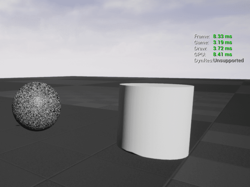
The render of a frame starts in the main game thread:
Game thread (CPU): it calculates all the transformations of the objects in the scene. This includes animations, physics, AI, and all the logic that happens in our application.
Draw thread (CPU): it calculates what to include in the rendering. This is mostly done on the CPU, but there are some parts on the GPU as well. The occlusion process happens in this thread and it happens per object. A list of all visible objects is built after 4 occlusion steps:
- Distance Culling - Removes objects further than a given distance from the camera
- Frustum Culling - Removes objects outside the camera frustum
- Precomputed Visibility - Divides the scene into a grid of cells and every cell stores what it could be visible from that position
- Occlusion Culling - Check the visibility state of every object, if it's occluded by another one at that moment
To debug these occlusion steps, you can type stat InitViews in the console command to see the expense and the counts of occluded objects of this render step. To open up the console command, the default key is the backtick `, or you have it at the bottom of the Output Log as well (Windows->Developer Tools->Output Log).
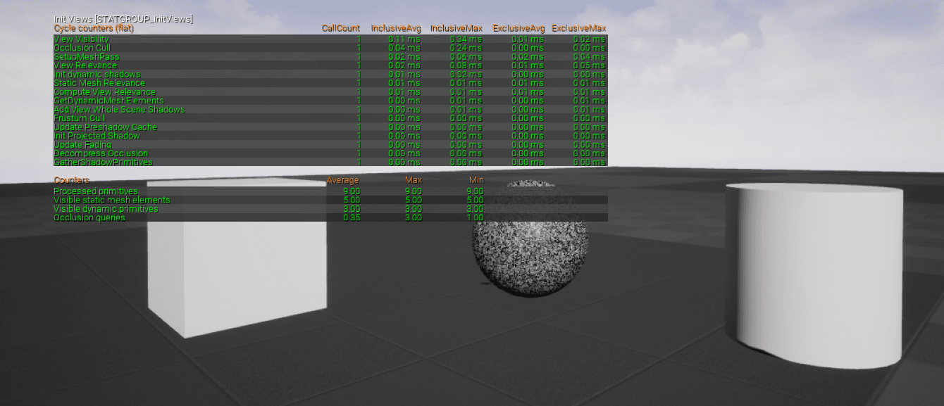
Now that the engine knows what objects need to be rendered and where they are, it remains to know in what order the renderer needs to render those: this is done as the first step in the next section.
Render thread (GPU): the geometry rendering starts. Unreal have both forward and deferred rendering paths.
The default one is the deferred rendering: the rendering pipeline is divided in passes, and the lighting calculation is postponed once all the objects are rendered into the GBuffer. Every render pass defines a different part of the renderer. For example, the base pass renders the material properties into different buffers, that can be reused later on within the light pass, which calculates the lighting of the scene. Finally, all passes are composed together to achieve the final result.
Forward rendering, instead, it does everything in the same pass, except for post-processes that are added at the end. This is simpler for handling transparency and it's usually faster for simple scenes that do not require a lot of dynamic lights.
Forward vs deferred is a big topic, and both have pros and cons that are outside the scope of this post. All you need to know is that Unreal uses deferred rendering as default, but you may prefer forward rendering when dealing with VR applications, especially on mobile.
The render starts with a prepass for depth calculation: the Prepass/Early Z Pass is done on the GPU that figures out which models will be displayed where. It consists of a pass of z-depth: when an object is projected on the screen, the depth (z-value) of a generated pixel is stored in a buffer (the z-buffer or depth buffer) representing its distance from the camera. This is needed to understand which object is on top of others and it could be useful to avoid overdrawing some pixels later in the pipeline.
Then, GPU starts to render object by object, firing a draw call. This consists of a group of polygons that shares the same properties. Between every drawcall, the render state could change (meaning that the render needs to set the different properties for the actual draw call). Behind the scene, Unreal sorts the drawcalls to optimize the number of state changes. The fewer changes the engine needs to do, the better are the performances. Usually, this optimization consists in grouping drawcalls by materials, and the engine does this automatically.
Drawcalls have a huge impact on performance: every time the render is done executing the commands, it needs to receive the new commands for the next call from the render thread and this adds significant overhead.
Typing stat RHI in the console command you can check the number of drawcalls that are called from the renderer. Broadly (because it depends on a lot of different variables) a reasonable number is 2000/3000 for a desktop application. 5000 is still acceptable for good hardware; over 10000 it's probably a problem. On mobile, a good number is far lower, about a few hundred.
Another very useful - and I would say essential - tool is RenderDoc: it's a free standalone graphics debugger that allows quick and easy single-frame capture of a single frame to make a detailed inspection of all the calls the application does. It works with every render API. Unreal has a plugin for it, see more here.
Here is a screenshot of a capture of a simple scene in Unreal:

On the left, you can see the Event browser that lists all the graphics API commands. In the Scene section there are the render passes, and if you expand a pass you'll find the list of draw calls for that step. On the right, there are the outputs of the selected pass: you can see the depth, and some of the GBuffer buffers filled in. As you can see on the left of the window, Unreal does a lot of passes for a frame. Even if you have 5 objects in the scene (the floor, the sky, and the three framed elements) the engine fires a lot of draw calls for all the other different passes.
This is a very big topic, so for drawcalls I would finish here. I highly suggest using RenderDoc to see how a frame is composed.
Bear in mind that Unreal Engine renders one primitive component at a time: the rendering unit is not an actor, but a primitive component. This means that when you have an actor blueprint with 5 static mesh components in it with a single material each, that will results in 5 draw calls (at least, it's actually 5 drawcalls for every pass the primitive is rendered into). Plus, if you assign multiple materials to the single primitive component, you'll end up having a draw call per each material.
From version 4.22, Unreal developed an automatic draw call merging system, but this works with some limitations (more here).
This is just an overview of the Unreal render process: to see more in detail effectively how the engine renders a frame, you can check this article: How Unreal renders a frame.
Rendering Elements
Let's see the main rendering elements that are important in real time rendering and how Unreal Engine deals with these.
Textures
It's important to understand what a texture is for the renderer, because it influences a lot the memory consumption of the application and the visual quality of the final image.
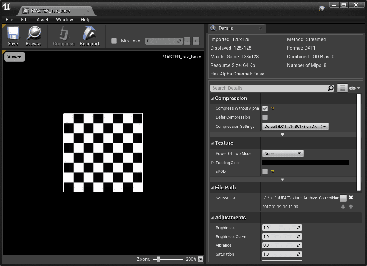
When rendering, we have limited memory and bandwidth: it's essential to compress an image before using it on the GPU. Unreal does this automatically during the file import. A texture is compressed with a compression algorithm that differs per platform: the most commonly used on PC are DXTC/BC (DirectX Texture Compression/Block Compression). In very simple words, these algorithms act by compressing blocks of pixels into smaller ones to store less information with a minimum loss percentage. Without digging more in technical details, what you need to know is that you can change the texture compression by opening a texture asset from the content browser.
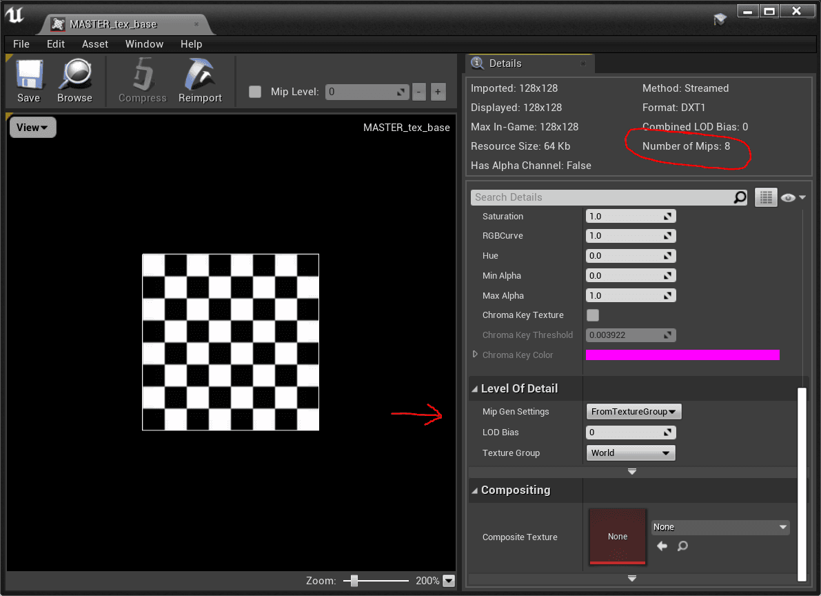
For every texture, the engine automatically creates mipmaps (or MIP maps). "MIP" stands for the Latin phrase multum in parvo, meaning "much in little", referring to the fact that mipmaps solve the texture minification/magnification problem, that creates a really annoying aliasing effect. These maps are generated by creating a smaller image with height and width a power of two smaller than the original one: every level is a quarter smaller in size and represents a mipmap level. To do this efficiently, textures should be a power of two (1024x1024, 512x512, 256x256 and so on). Please note that it's not necessary that the image is squared, it could be rectangular as well: the important thing is that the sizes must be a power of two (for instance, a texture could be 256x1024, and that's still good for mipmaps generation). Here you can see these details in Unreal:
Pipeline Stages and Shaders
Every time a render engine fires a draw call, the pipeline stage starts for that object(s). This screenshot from Renderdoc shows you the pipeline stages:

Some stages have their shader, which essentially is a program that runs on the GPU with some inputs from the previous stage and outputs information for the next stage. The programming language used to code a shader depend on the platform it should run: on Windows, HLSL (High-Level Shading Language) is used by the DirectX API. On Mac, the Metal API uses its own Metal Shading Language (MSL). There are of course cross-platform graphics API that has their language, like OpenGL that has GLSL (OpenGL Shading Language).
Shaders in Unreal are written in HLSL (Hig Level Shading Language): they are stored in the Engine/Shaders folder in the form of USF files (Unreal Shader File). The material editor uses these files as templates to create the final shader that includes user customization from the material editor nodes. So when a user creates a material using the material editor, the Engine compiles this to HLSL code and fills the template that it has depending on the shading model we selected.
The most important and most used shaders in real time rendering are the Vertex Shader and the Pixel Shader.
As you can see in the image above, the first shader is the vertex shader: is the program that runs every vertex (of the object that is being rendered) coming from the input assembler (the first stage of the pipeline: IA in the image). In the simplest case, it calculates the transformations of the vertices from the object space to the world space. It can get more complicated as it can offset and move vertices depending on clothes simulation or wind parameters, for example. Performance wise, the more vertices your polygon has, the more expensive this stage is.
Hull, Domain and Geometry shaders (respectively HS, DS and GS in the image) are less common, mainly used for the tessellation stages. I'll skip these for this post.
The pixel shaders is the other important one: it runs for every pixel the object occupies in the final image. These pixels are calculated in the rasterization stage (the rasterizer on the image), that handles the 3D vertices data and project those into the 2D screen, resulting in a bunch of pixels that are occupied by the rendered object, and it gives this as input for the pixel shader. I'm not going to focus on the rasterizer, because it's something you can't customize with the shader, but you can just set some state of it, like culling mode for example.
The pixel shader runs all sorts of calculations that we need to do for the final material. Here is where lighting and shading happens. Performance wise, the more pixels the object covers onto the screen the more expensive it will be this stage, because the shader will be called a lot of times.
More on this in the Materials section.
Materials
Unreal Engine material system relies on physically based shading. It means that the lighting and shading algorithms used in the engine approximate the physical interaction between light and materials.
When calculating the shading, UE4 uses algorithms and units that are as close to physically accurate as possible. For example, light intensity is provided in lumens and the light intensity falls off at a rate that follows the inverse square law.
Materials are defined using albedo, roughness, metallic and specular parameters that reflect physical properties that define a material in reality.
More on this here: Physically Based Shading.
A material/shader has a max number of textures up to 16, which only 13 can be used (the others are used internally by the engine). The more textures you have for a material, the more memory it will occupy. Performance wise, this could cause freezes and lags when loading that memory on the GPU, but note that will not affect a constant drop of the fps.
In the material editor, you can see how many samplers you're using by looking at the stats tab at the bottom.
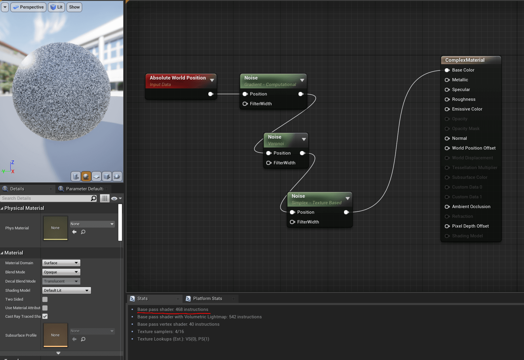
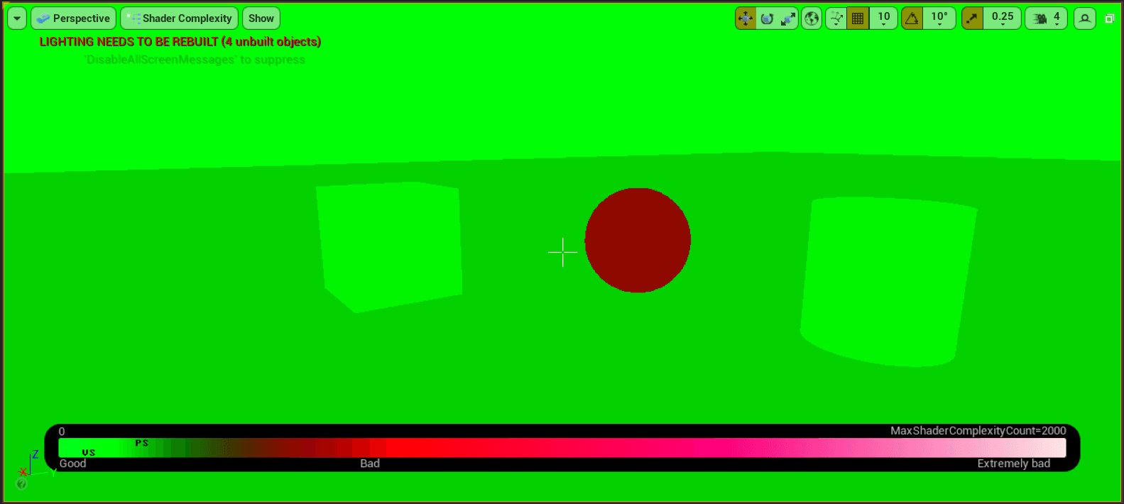
A material is more expensive the more pixels it covers on the screen. This can be seen looking at the Shader Complexity visualization in the engine.
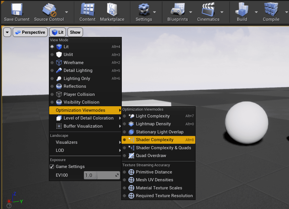
The complexity is measured in shader instructions: normally should be around 100/200; generally few hundred is fine, and close to thousands it can be a problem. For instance, look at the images below; the material looks simple but contains three noise nodes that are expensive, resulting in 468 instructions: now look at how it is shown in complexity view mode.
Reflections
Reflections are difficult in real time because they require the scene to be rendered several times for every reflection setup. To make this works, some techniques simulate reflection effects trying to not impact heavily on performances.
In Unreal Engine, there are three different systems for doing real time reflections. They are combined and blended together to achieve the best final image quality. The three systems are:
-
Reflection Capture
It's an actor that works capturing a static cubemap at its location. As a solution is pretty fast but the visual result is good only if you are in the same position as the reflection capture. The moment you move away from it, the camera won't match the position and the reflections start to look odd. Usually you don't see this because of the combinations with other systems (explained below). Performance wise is the best you can do since it is precalculated it has almost 0 costs at runtime. You can increase the size of the generated cubemap to have a better result. A reflection capture only works within the range of the reflection actor: all the objects inside that range will sample from it. Otherwise, objects outside will not receive any reflection.
-
Planar Reflections
These are not very common, fairly never used. They are similar to the reflection captures, but differ as they capture from a plane and they can be set to real time. Because of this, planar reflections can be heavy, but are good for flat surfaces on a limited area (good for a mirror, bad for an ocean surface). The actor for this system is the planar reflection actor that you can set to realtime enabling the
capture every frameoption. -
Screen Space Reflections (SSR)
This is the default system. It's a screen space effect and its precision does not depend on the camera position. It's a real time effect that only shows reflection of what is visible in the scene. As it is a screen space effect, it affects the entire world, it doesn't have a range. Problems are: it does have a cost and it's noisy. It won't reflect objects that are not visible on screen (so if something is being culled, it won't be reflected, but most of the time you want have it reflected).
Every system has pros and cons: you should combine them for the best result.
Performance implications: having many reflections captures may slowdown the level loading time. Try to not overlap reflection captures because otherwise the pixel shaders involved will end up doing a lot of sampling from different cubemaps and it has to combine them together, resulting in a lot of repeated calculations. Generally, planar reflections should be avoided. For projects that need to run on limited hardware, try to avoid SSR, otherwise you can push it on desktop or high-level targets in favor of the other systems.
Unreal does have also the skylight actor that provides a backup if you need to place a lot of reflection captures in your scene. It will capture a cubemap for the entire world within the sky distance threshold. If there is an object in the scene that is not affected by any kind of reflection system, it will back up on the skylight.
Lighting
Lighting is another big topic of real time rendering. It's really difficult to calculate the light effects, so the calculation is split between precalculated and real time (like reflections system does). Calculations are heavy especially because of shadows.
Unreal Engine allows you to have three types of lights:
Static Lighting
It's precalculated and stores information onto lightmaps. This is fast (it costs almost 0 at runtime) but increases the application memory. It takes a long time to precalculate and it has to be redone every time something changes.
Take in consideration that you need a special UV map (i.e. the process that permits any 3D polygon to have textures projected onto it - if you are unfamiliar with UV mapping, see more here) to use lightmaps: every model needs to have dedicated lightmap UVs that needs be between 0 and 1 and they shouldn't have any overlap between them. Luckily, Unreal Engine can generate automatically these lightmap UVs, you can see this in the detail panel of the static mesh editor:
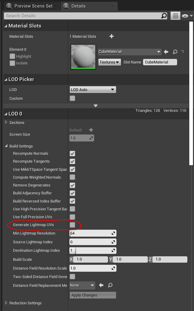
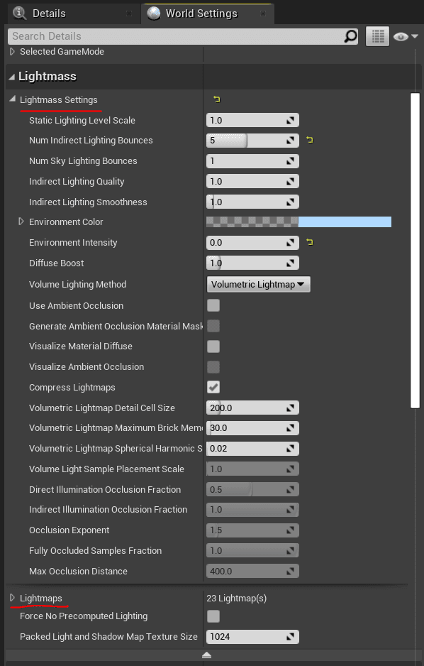
Since it's precalculated (so it is offline, not runtime), static lighting handles radiosity and global illumination, giving a great quality result. The quality depends mostly on the UV and the size of the lightmap (the maximum size of a texture is 8k, so consider this for when you have a big object). Static lighting is generated using the lightmass, which is a standalone application that handles the rendering and the shadow baking. It supports distributed rendering on network and requires a lightmass importance volume placed in the scene, where you can tweak the settings in the lightmass section. Anything within the volume will get higher quality lighting calculations. So you should place one or even multiples boxes where it's important to have more quality. During this process, an ILC (indirect lighting cache) is built with the lighting information. This is used for dynamic objects that need to receive static lighting. The dynamic models will sample from the ILC cache, which is a volume full of samples with the indirect lighting value at that point in space. All the ligthmaps are packed in atlases: you can control these and change parameters by the build lighting option and the quality settings in the lightmass (in the world settings).
Performance implications: 1 or 50000 static lights in the scene doesn't matter. It performs the same at runtime since they are precalculated, but it heavily affects memory and filesize. The more resolution you have for lightmaps, the more it takes to bake.
Dynamic Lighting
Here dynamic means real time. Lighting is calculated at run time, and shadows as well. This is really heavy since it does not precalculate anything. For this you have a lot of different solutions, so it's all a matter of combinations between different techniques, like it is for reflections. Quality wise, dynamic shadows are not usually that good. Dynamic lighting most of the time doesn't do any soft shadows or global illumination, because of the time it requires to calculate that.
Shadows are what it really takes time to calculate. Unreal Engine gives us four main types of dynamic shadows:
- Regular dynamic shadows: coming from a movable light. They are usually sharp (and so unrealistic) because there's no way of replicating the multiple bounces lights that generate a soft shadow.
- Per object shadow (stationary light): blend between static and dynamic system. It creates a lightmap for what we know that light doesn't change, and then also renders dynamic shadows on top. The result is much better (and softer) than a full dynamic one, but a higher cost.
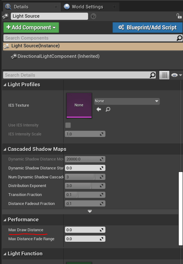
- Cascaded shadow maps (CSM): can only be run on directional light shadows. It works well in distance and open fields because it's based on splitting the shadow maps in distance ranges from the camera. Different shadow maps are calculated with more precision closer to the camera, depending on how we set the cascade distance options.
- Distance field shadows: uses the distance fields of an object when calculating shadows, instead of the geometry itself. It's very imprecise but very cheap even compared to CSM. Distance fields can calculate shadows in a cheaper way because they store distances on a volume textures and the resolution of the textures defines the quality of the shadows. The result is not very detailed, so it is usually used for distant shadows only.
To activate this in Unreal Engine, check the
Generate Mesh Distance fieldsoption in the project setting. It may take time to generate DF the first time for all the objects.
There are also other types of shadows that are less used:
- Inset shadows: same per object shadows but more precise for dynamic objects
- contact shadows: fine contact shadows, useful for small details
- capsule shadows: simplified shadows very cheap underneath models
For dynamic lighting, point lights are rendered as spheres: the size of the sphere is the range of the actor in the scene. The sphere is rendered and used as a mask in the deferred shading pipeline. All the objects within the sphere range need to run the pixel shaders to calculate lighting pass. You can check the light sphere masks looking at the light complexity buffer in the optimizations view modes. Performance wise, try to not overlap dynamic lights, otherwise some pixel could run the same calculations again and again for each light. Shadow maps are really heavy in general, since the renderer has to render the scene depth for the point of view of the light into a cubemap - for every light.
Performance implications: dynamic lights are more expensive in forward rendering than in deferred rendering due to the nature of the two different paths. The more pixels the lights cover in the screen, the more it costs: the radius needs to be as small as possible and you need to avoid overlaps between light actors. The most expensive things are shadows: in a very easy way, turn off shadows if you don't need it to gain performance.
The polycount of objects matter for dynamic shadows, because of the shadow maps: use DF or CSM, or adjust properly the max draw distance settings to every lights, so that it can be culled to avoid useless calculations.
Finally, as usual, the best results are achieved with a mix of static and dynamic lighting. Use static for distant lights and spots where you need precise indirect lighting and your light is not mean to change. Use dynamic lights when you really need the light to change at runtime; use it for interactive and animated objects that need to be shadowed and are closer to the camera. Always try to fake and tweak lighting with static lights to have better performances.
Transparency
Transparency is one of the biggest performance killer of real time renderer.
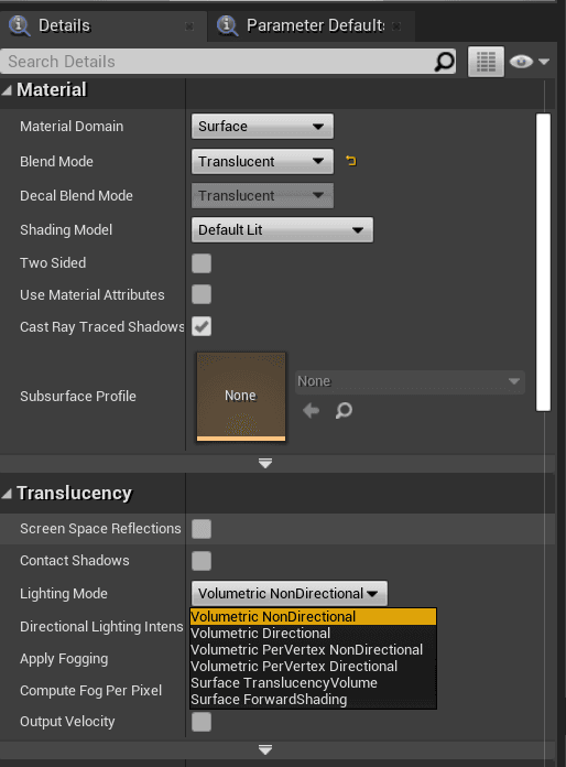
Deferred rendering has difficulties with transparency, since transparent objects are delayed at the end of the pipeline stages but even at that point the GBuffer doesn't have enough information to render translucency objects properly. Usually, transparency is rendered in forward rendering and then composed on top of the rest. Check the lighting mode in the translucency section in the material editor: these modes are the options that Unreal gives us to render transparent objects.
Other than the pixel shader cost (that needs to run more now on top of the already rendered scene) there is also the problem of the render object order.
The easiest and fastest mode of transparency is the masked mode: in this case, an object is either fully visible or not visible at all, so it's very easy for the renderer to decide which pixel covers what object. If you need transparency values to be between 0 and 1, try at least to use the unlit shading, to avoid repeating all the lighting calculations for transparent objects only.
Generally, you should reduce the shader instruction count for translucent objects as much as you can.
Post Processing
Post Process is a term that is most of the time used to represent a screen pass shader/effect. Basically, it's called post process a render pass that runs after the main pass, where usually the whole scene is already rendered. In forward rendering this concept is better defined, since the scene is rendered at once with all the lights calculations and shadows and transparency done in the same render pass. In deferred rendering, there are a lot of render passes, so saying post process means a little bit less. So in general, a post process is better defined as a screen pass shader that is applied at the end of the rendering pipeline to the whole frame. It's in a simple way a pixel shader that runs for every pixel of the final image, not object related.
Unreal has a lot of post processes, the more used are: bloom, depth of field, lens flares, vignette, tonemapping, motion blur, exposure, and a lot more. To see all of them, drag in your scene a post process volume: in the details panel, you can enable/disable and edit all the available effects. Here is an image showing some of them, as you can see you have a lot of effects here:
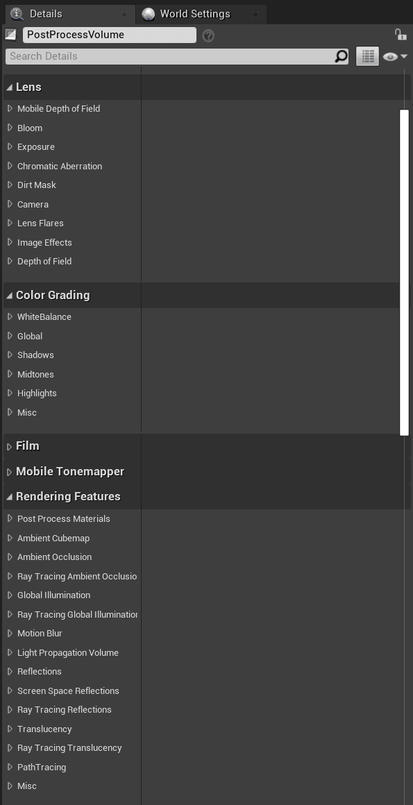
These effects can be applied to the entire scene if you select the Infinite Extent (Unbound) option in that panel, otherwise they will be applied only when the camera is inside the volume.
However, you can create your post process material the same way you create a material, selecting the shader type to post process in the material editor. In fact, a post process effect is simply a pixel shader applied to the entire screen. When creating the post process material you'll get access to different parameters compared to a mesh material. Since it will run at the end of the rendering pipeline, you'll have access to the scene textures like the scene color and the depth, but you cannot access to any of the geometry parameters, since all of the objects are already rendered in the previous passes.
Conclusions
In this article, I wrote down an high-level overview of the Unreal Engine rendering process and shown some tips to consider when dealing with performances. What I would like to do next is describing in detail some interesting aspects of the renderer that we faced while developing new graphics features at Zuru Tech.