


In this article I will talk about our solution to cut geometry at runtime in Unreal Engine 4 (UE4) and how we speed up the process using a compute shader. I would like to use this article as a resource for anyone who needs to add a compute shader and need to manage buffer read/write between GPU and CPU in Unreal Engine. You can find many good resources about it (an honorable mention goes to Temaran) but you need to make a collage from multiple sources so hopefully, this could make your life a bit simpler. And I hope that could help also if you are facing similar geometric processing in your project.
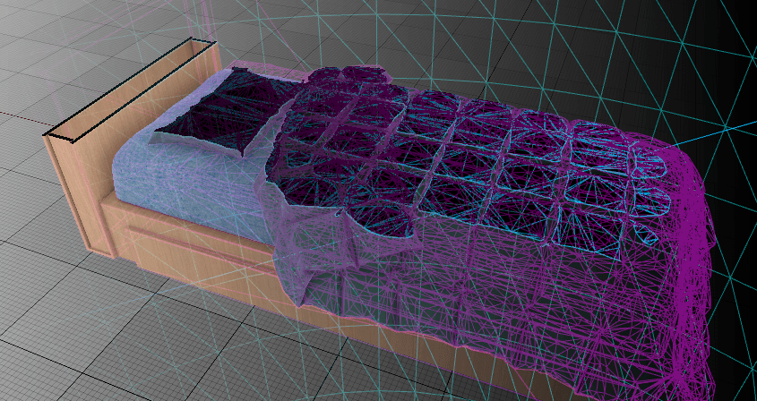
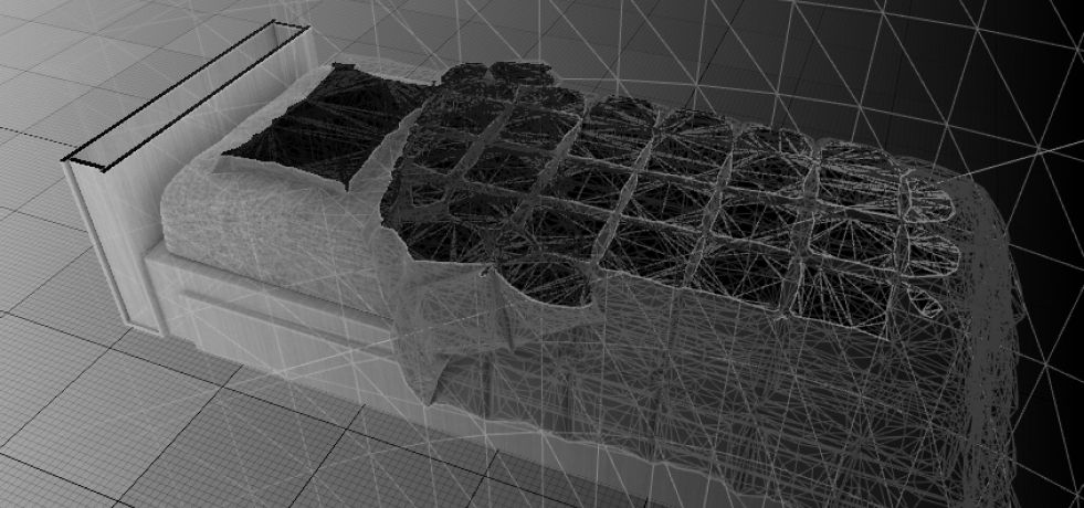
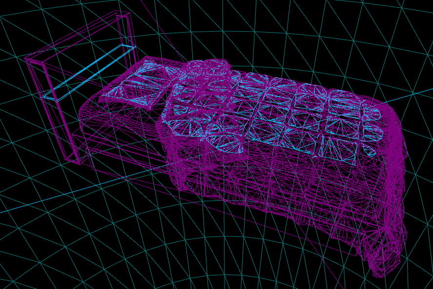
The standard approach is to mask the material and use the back-faces to display the (fake) cross-section surface. This is possible only if you have manifold geometry. If, for example, you have intersections between triangles of the same mesh you cannot rely on this technique.
After some analysis, we end up deciding to build the actual geometry to display the cross-section.
As this is our first iteration I will place some disclaimer in the article to notify about things that I'd like to explore better. Since it performs well enough for our purpose it's not sure that updates will come soon but it's definitely something that I want to do as soon as I can.
Table of Contents:
The Pipeline
Since it could be heavy to process complex geometry, we split the work between GPU and CPU to take advantage of the high parallelization offered by the former architecture.

Compute intersection
Shader declaration
Remember that global shaders must be loaded right after the engine, so you need to put them in a module with the LoadingPhase set to PostConfigInit.
Add in the module the virtual path for your shader:
FString ModuleShaderDir = FPaths::Combine(FPaths::ProjectDir(), TEXT("Source/Presenter3D/Shaders"));
AddShaderSourceDirectoryMapping(TEXT("/Presenter3D"), ModuleShaderDir);
I created the class FMeshPlaneIntersectionCS, derived from FGlobalShader, that deals with C++ to HLSL communication, inside which there are:
- parameters declaration:
DECLARE_GLOBAL_SHADER(FMeshPlaneIntersectionCS); SHADER_USE_PARAMETER_STRUCT(FMeshPlaneIntersectionCS, FGlobalShader); BEGIN_SHADER_PARAMETER_STRUCT(FParameters, ) SHADER_PARAMETER(FVector4, SectionPlane) SHADER_PARAMETER_SRV(Buffer<FVector>, VertexBuffer) SHADER_PARAMETER_SRV(Buffer<uint32>, IndexBuffer) SHADER_PARAMETER_RDG_BUFFER_UAV(RWStructuredBuffer<FVector>, CutSegmentsA) SHADER_PARAMETER_RDG_BUFFER_UAV(RWStructuredBuffer<FVector>, CutSegmentsB) SHADER_PARAMETER_RDG_BUFFER_UAV(RWStructuredBuffer<bool>, CutSegmentsValidation) END_SHADER_PARAMETER_STRUCT() - setup permutations (to avoid compiling for platform that you don't use or simply don't support your functionality):
static bool ShouldCompilePermutation(const FGlobalShaderPermutationParameters& Parameters) { return IsFeatureLevelSupported(Parameters.Platform, ERHIFeatureLevel::SM5); } - setup compilation environment:
About threadgroups, I will come back later.static inline void ModifyCompilationEnvironment(const FGlobalShaderPermutationParameters& Parameters, FShaderCompilerEnvironment& OutEnvironment) { FGlobalShader::ModifyCompilationEnvironment(Parameters, OutEnvironment); OutEnvironment.SetDefine(TEXT("THREADGROUPSIZE_X"), 1); OutEnvironment.SetDefine(TEXT("THREADGROUPSIZE_Y"), 1); OutEnvironment.SetDefine(TEXT("THREADGROUPSIZE_Z"), 1); }
After this class I actually declared the shader:
IMPLEMENT_GLOBAL_SHADER(FMeshPlaneIntersectionCS, "/Presenter3D/MeshPlaneIntersection.usf", "MainCS", SF_Compute);
Shader usage
FMeshPlaneIntersection is the class that act as a manager for our shader:
class PRESENTER3D_API FMeshPlaneIntersection {
public:
    TArray<TTuple<FVector, FVector>> PerformIntersection(FPositionVertexBuffer*& vertexBuffer, FRawStaticIndexBuffer*& indexBuffer, FPlane sectionPlane);

private:
    void _runComputeShader_RenderThread(
        FRHICommandListImmediate& rhiCmdList, FPositionVertexBuffer* vertexBuffer, FRawStaticIndexBuffer* indexBuffer, FPlane sectionPlane);

    // Copies an FPooledRDGBuffer
    static void _copyBuffer(FRHICommandListImmediate& rhiCmdList, TRefCountPtr<FPooledRDGBuffer>& source, void* dest, SIZE_T size);

    TArray<FVector> _outSegmentsA;
    TArray<FVector> _outSegmentsB;
    TArray<int> _outSegmentsValidation;
};
Inside Render Thread
Disclaimer: This flow works only if you set on your mesh "Allow CPU Access" at true. Otherwise, RenderData (the interface that gives access to the mesh buffers) in the cooked version of the asset will be available only in GPU. So to read them you have to dialogue with RenderThread. I didn't tested yet the performance hit of this specific change (if there is any).
Let's start from _runComputeShader_RenderThread.
Here is where the compute shader is executed, but before dispatch it, you need to setup properly input and output.
First we need to make our GraphBuilder and allocate memory:
FMemMark Mark(FMemStack::Get());
FRDGBuilder graphBuilder(rhiCmdList);
FMeshPlaneIntersectionCS::FParameters* PassParameters = graphBuilder.AllocParameters<FMeshPlaneIntersectionCS::FParameters>();
Giving input to the shader is simple, we just need to ask the shader resource view of the buffers to the engine, and of course give our cut plane from the input:
PassParameters->SectionPlane = FVector4(sectionPlane, sectionPlane.W);
PassParameters->VertexBuffer = vertexBuffer->GetSRV();
PassParameters->IndexBuffer = rhiCmdList.CreateShaderResourceView(indexBuffer->IndexBufferRHI);
Setting up the output buffers require a bit more effort. But before going on I'll talk about what we want as output: the parallelization is triangle based. So every thread will compute the intersection between one triangle of the mesh and the plane and output the start (A) and end (B) points of the resulting segment. To skip missed triangles (or monodimensional output) we fill also a validation buffer that stores the information so that when we collect shader output we can discard useless data. So, the next thing is to set the output array lenght now:
uint32 outBufferSize = indexBuffer->GetNumIndices() / 3;
And than we can start building our buffers, I'll show one as an example:
_outSegmentsA.Empty();
_outSegmentsA.Init(FVector(0, 0, 0), outBufferSize);
auto rdgOutSegmentsA = CreateStructuredBuffer(graphBuilder, TEXT("CutSegmentsA"), sizeof(FVector), outBufferSize, _outSegmentsA.GetData(),
    sizeof(FVector) * outBufferSize, ERDGInitialDataFlags::None);
auto uavOutSegmentsA = graphBuilder.CreateUAV(rdgOutSegmentsA);
It's almost the same for CutSegmentsB and SegmentsValidation, then we can bind UAV buffers to the shader (set them to PassParameters struct as the input).
Now that shader bindings are done we need to get a reference to our shader from the global shader map and setup threadgroups:
TShaderMapRef<FMeshPlaneIntersectionCS> ComputeShader(GetGlobalShaderMap(GMaxRHIFeatureLevel));
FIntVector GroupCounts = FIntVector(outBufferSize, 1, 1);
Disclaimer: For simplicity in this first iteration I just added the needed number of threads on one dimension. This needs some attention to be sure that GPU resources are not wasted. If you are interested in a look at this without waiting for future updates here's a useful link that I've found: https://gpuopen.com/learn/optimizing-gpu-occupancy-resource-usage-large-thread-groups/
Finally we can add our shader to the command list:
FComputeShaderUtils::AddPass(graphBuilder, RDG_EVENT_NAME("MeshPlaneIntersection"), ComputeShader, PassParameters, GroupCounts);
Than we add the extraction commands for our output (an example for CutSegmentsA):
TRefCountPtr<FPooledRDGBuffer> pooled_verticiesA;
graphBuilder.QueueBufferExtraction(rdgOutSegmentsA, &pooled_verticiesA, FRDGResourceState::EAccess::Read, FRDGResourceState::EPipeline::Compute);
And here we go, just "pull the Execute() trigger" on the Graph Builder and let the GPU do the math for you!
Now, for all three output buffers, we need to copy data from the their FPooledRDGBuffer to our TArray that we can go on and use them on CPU. That's what _copyBuffer does:
void* psource = rhiCmdList.LockStructuredBuffer(source->StructuredBuffer, 0, size, RLM_ReadOnly);
FMemory::Memcpy(dest, psource, size);
rhiCmdList.UnlockStructuredBuffer(source->StructuredBuffer);
Shader code
There's not much to say, just some math and float precision managing. Notice that the buffer's operations are atomic so you must be more explicit on operations than you could be for example working with an array on a pixel shader.
#define PRECISION_TOLERANCE 0.0001
#define SMALL_NUMBER 1.e-8f

bool AlmostEqual(in float3 inP, in float3 evalP)
{
    return abs(inP.x - evalP.x) <= PRECISION_TOLERANCE && abs(inP.y - evalP.y) <= PRECISION_TOLERANCE && abs(inP.z - evalP.z) <= PRECISION_TOLERANCE;
}

void AddUnique(in out float3 list[2], in out int arrayPos, in float3 evalP)
{
    if (arrayPos > 1)
    {
        for (int c = 0; c < arrayPos; ++c)
        {
            if (AlmostEqual(list[c], evalP))
            {
                return;
            }
        }
    }
    list[arrayPos] = evalP;
    ++arrayPos;
}

float DistFromPlane(float3 P)
{
    return dot(normalize(SectionPlane.xyz), P) - SectionPlane.w;
}

bool GetSegmentPlaneIntersection(float3 P1, float3 P2, out float3 outP)
{
    float d1 = DistFromPlane(P1), d2 = DistFromPlane(P2);

    if (d1 * d2 > 0)
    {
        return false; // Points on the same side of plane
    }
    if (abs(d1) <= PRECISION_TOLERANCE && abs(d2) <= PRECISION_TOLERANCE)
    {
        return false; // Points aligned with plane
    }

    float t = d1 / (d1 - d2);
    outP = P1 + t * (P2 - P1);
    return true;
}

void TrianglePlaneIntersection(float3 A, float3 B, float3 C, out bool isTriangleIntersected, out float3 outP1, out float3 outP2)
{
    float3 IntersectionPoint;
    float3 OutSegment[2];
    isTriangleIntersected = false;
    int i = 0;

    if (GetSegmentPlaneIntersection(A, B, IntersectionPoint))
    {
        AddUnique(OutSegment, i, IntersectionPoint);
    }

    if (GetSegmentPlaneIntersection(B, C, IntersectionPoint))
    {
        AddUnique(OutSegment, i, IntersectionPoint);
    }

    if (GetSegmentPlaneIntersection(C, A, IntersectionPoint))
    {
        AddUnique(OutSegment, i, IntersectionPoint);
    }

    if (i == 2)
    {
        outP1 = OutSegment[0];
        outP2 = OutSegment[1];
        isTriangleIntersected = true;
    }
}

[numthreads(THREADGROUPSIZE_X, THREADGROUPSIZE_Y, THREADGROUPSIZE_Z)]
void MainCS(uint3 ThreadId : SV_DispatchThreadID)
{
    float3 A, B, C;
    A.x = VertexBuffer[IndexBuffer[ThreadId.x * 3] * 3];
    A.y = VertexBuffer[IndexBuffer[ThreadId.x * 3] * 3 + 1];
    A.z = VertexBuffer[IndexBuffer[ThreadId.x * 3] * 3 + 2];

    B.x = VertexBuffer[IndexBuffer[ThreadId.x * 3 + 1] * 3];
    B.y = VertexBuffer[IndexBuffer[ThreadId.x * 3 + 1] * 3 + 1];
    B.z = VertexBuffer[IndexBuffer[ThreadId.x * 3 + 1] * 3 + 2];

    C.x = VertexBuffer[IndexBuffer[ThreadId.x * 3 + 2] * 3];
    C.y = VertexBuffer[IndexBuffer[ThreadId.x * 3 + 2] * 3 + 1];
    C.z = VertexBuffer[IndexBuffer[ThreadId.x * 3 + 2] * 3 + 2];

    bool isTriangleIntersected;
    float3 outA;
    float3 outB;

    TrianglePlaneIntersection(A, B, C, isTriangleIntersected, outA, outB);

    CutSegmentsA[ThreadId.x * 3] = outA.x;
    CutSegmentsA[ThreadId.x * 3 + 1] = outA.y;
    CutSegmentsA[ThreadId.x * 3 + 2] = outA.z;

    CutSegmentsB[ThreadId.x * 3] = outB.x;
    CutSegmentsB[ThreadId.x * 3 + 1] = outB.y;
    CutSegmentsB[ThreadId.x * 3 + 2] = outB.z;

    CutSegmentsValidation[ThreadId.x] = isTriangleIntersected ? 0 : -1;
}
Outer interface
Usage it's as simple as:
auto cutter = new (FMeshPlaneIntersection);
TArray<TTuple<FVector, FVector>> segments = cutter->PerformIntersection(vertexBuffer, indexBuffer, sectionPlane);
delete (cutter);
(Of course, you could change the output format with a data structure more convenient for your needs)
Our _runComputeShader_RenderThread is sent to the RenderThread through the ENQUEUE_RENDER_COMMAND macro.
To manage the async operation you have multiple choice, to keep the interface simple I managed it using the render fences, waiting for the result of the computation. If it's a solution compatible with you project do this:
FRenderCommandFence Fence;
ENQUEUE_RENDER_COMMAND(PerformGPUIntersection)
([this, vertexBuffer, indexBuffer, sectionPlane](
        FRHICommandListImmediate& rhiCmdList) { this->_runComputeShader_RenderThread(rhiCmdList, vertexBuffer, indexBuffer, sectionPlane); });
Fence.BeginFence();
Fence.Wait();
After this, you have the class members' arrays filled with the output of the compute shader ready to be used.
Geometry generation
This is the update pipeline of the cross-section component:
"UStaticMesh* inMesh;"
"FVector sectionPlaneNormal;"
FVector sectionPlaneLocalOffset = GetComponentTransform().InverseTransformPosition("Cut offset");
FPlane sectionPlaneLocal = FPlane(sectionPlaneLocalOffset, sectionPlaneNormal);
TArray<TArray<FVector>> loops;
if (_checkBBoxPlaneIntersection(inMesh, sectionPlaneLocal)) {
    TArray<TTuple<FVector, FVector>> segments;
    // Cut triangles (performed in shader)
    _cutGeometry(inMesh, sectionPlaneLocal, segments);
    // Sort segments and populate loops
    _sortSegments(segments, loops);
    // Split loops for non-manifold geometry (intersecting vertex)
    _splitNonManifoldVertices(loops);
    // Split loops for non-manifold geometry (intersecting segments)
    _splitNonManifoldSegments(loops);
}
_updateGeometry(loops, sectionPlaneLocal);
As you noticed to avoid wasting time converting vertex buffer positions from local to world I opted for converting just the plane into local.
The checkBBoxPlaneIntersection is a simple optimization to avoid work if the plane does not intersect our mesh.
_cutGeometry you already know what it does. So let's go through the other steps.
Sorting
First, we need to reorder all the segments that compute shaders sent to us to get one (or more) closed loops that represent the border of our cross-section. I'd like to find some smart algorithm that simplifies the problem but for now, the only solution is to, starting from a segment, check for matching points, and put the new one at the end or the beginning of the collected sorted segments. If no match was found but there are still not sorted elements then you start a new loop. And so on...
Fix non-manifold loops
Sadly in our specific project, we could get self-intersecting loops, with the intersection point both on shared vertices or between two segments. Let's see how to deal with them:
First, solve it per vertex. We go through every loop and for each point, we search the first point with an equal value in the loop; if we found one it means there's a closed path inside the loop so we detach it and add it at the end of the list.
Then solve it per segment. It is almost the same process used for the vertex, but applied on segments described by subsequent points. We check if they are intersecting and, in that case, we compute the intersection point, add it to the main loop (in 2nd position, because it belongs to the two segments evaluated) and detach the inner one.
Disclaimer: This is another part that I'd like to explore more since it's too much brute force and I'm sure it could be optimized.
This is how we check intersections:
bool UDCGraphicsUtils::CheckSegmentsIntersection(const FVector& A, const FVector& B, const FVector& C, const FVector& D) {
    return (ccw(A, C, D) != ccw(B, C, D)) && (ccw(A, B, C) != ccw(A, B, D));
}
bool UDCGraphicsUtils::ccw(const FVector& A, const FVector& B, const FVector& C) {
    return (C.Y - A.Y) * (B.X - A.X) > (B.Y - A.Y) * (C.X - A.X);
}
And if the result is true this is how we compute the intersection point:
FVector UDCGraphicsUtils::GetSegmentsIntersectionPoint(const FVector& A, const FVector& B, const FVector& C, const FVector& D) {
    const FVector ba = B - A;
    const FVector dc = D - C;
    const float q = FVector::DotProduct(FVector::CrossProduct(dc, dc), FVector::CrossProduct(ba, dc)) / FVector::CrossProduct(ba, dc).Size();
    return A + (B - A) * FVector(q);
}
Deals with holes and concentric loops
I initially planned to manage this but since we didn't have geometry with this behavior I removed it to reduce performance cost. Anyway, the flow was:
- check for bounding box size of the loops
- check for every loop if his BB is entirely contained in other loop's BB
- store the result
- in the triangulation phase, we simply check if a loop has "fathers" and how many, if the number of the father is even then we fill the loops with triangles, otherwise not
Build mesh section
To triangulate the loops I didn't use any particular triangulation algorithm since we can rely on Clip2Tri library in our project. Maybe in a future update, I will expand this section.
Conclusion
The article described how I solved the problem of cut geometry at runtime using Unreal Engine 4. There are still some part of the code that might be improved and that require, perhaps, a better analysis (each of them highlighted with a disclaimer), but in this article I used an hands-on approach to describe how I solved it, so to be helpful to every other UE4 developer that's facing a similar challenge.